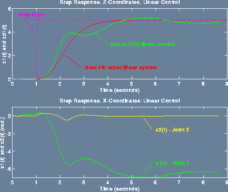
The first plot shown below is for linear control. It is a step
response. The controller first balances Link 1 at an unstable
equilibrium point. It is then commanded to move Link 1 one
revolution. This command is "aggressive," and causes Link 1 to move
very fast. Note the poor performance between 2 and 3 seconds, where
Link 1 changes direction. This occurs because Link 1 attains a high
velocity, so the centripetal force acting on link 2, being
proportional to the square of this velocity, (it is nonlinear)
becomes large. Furthermore, it acts in the same direction as gravity,
i.e., in a destabilizing direction. The linear controller doesn't
"know" about this force, can't compensate for it, and therefore
provides poor performance. For this experiment, the poles are placed
at s=-3.

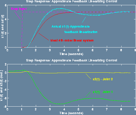
The second plot is of a nonlinear controller which partially compensates the nonlinear gravity effects and the nonlinear Coriolis and centripetal forces. The pendulum is not feedback linearizable, and therefore, it is not obvious how to compensate these destabilizing forces. (If it were feedback linearizable, we would be able to cancel all the nonlinear forces, and cause the pendulum to behave as a linear system, whose step response is shown in red in both figures.) Since this is not achievable, we have implemented an approximate feedback linearization, with the "outer-loop" poles at s=-3, for sake of comparison. Note the smoothness of the transient - link 1 does not change direction between 2 and 3 seconds.
The code that implements the controller occupies
about 32 Kbytes of TI 320C30 memory, and is quite computationally
complex. All of it has to be executed each sample period, i.e., in
1/200 of a second. The DSP can do this easily.

Scott Bortoff, bortoff@control.toronto.edu